

This step-by-step guide shows how to service your AVA Master P60-P80. Both Master 1.0 and Master 2.0.
Servicing your unit improves long-term performance, can help resolve frost damage and comes with the added benefit of extending your warranty by another 5 years*
Importantly: self-repair does not void warranty.
The service itself doesn’t involve many steps, but each one is described in detail to make the process as easy as possible for you – and to ensure the best possible result. We recommend reading through all the steps before you begin, so you understand the procedure and have the necessary tools to complete the task.
Always unplug the pressure washer from both the mains power and the water inlet before starting the service.
Click here to read our article regarding safety
Even though power and water are disconnected there may be pressurized water in the hose. Discharge this pressure by pulling the trigger on the gun in a safe direction.
Make sure your work area is clean and appropriate for the work you are about to do. There will usually be a small amount of water inside the pump and hose.
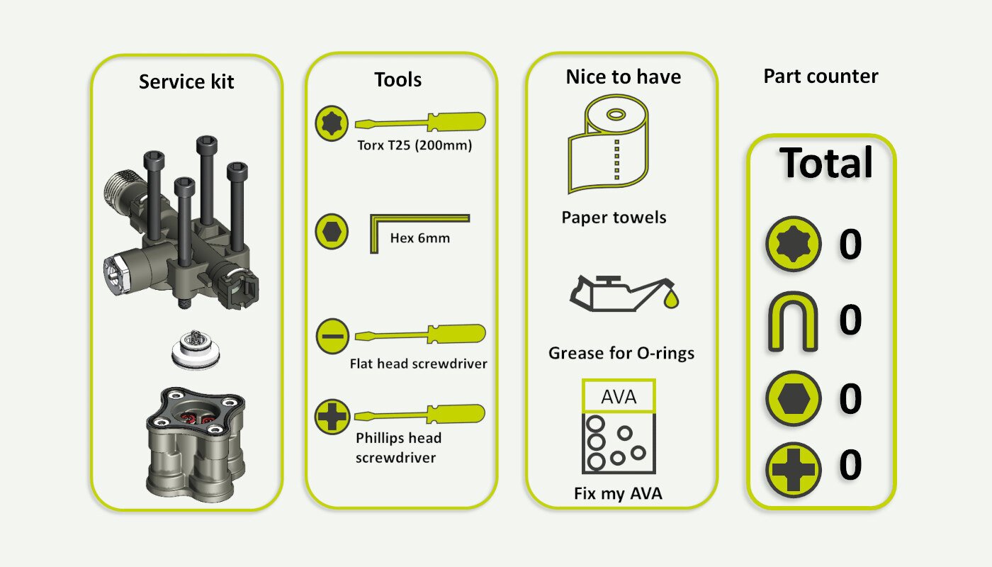
00. Parts and tools
An overview of what is needed to do this service.
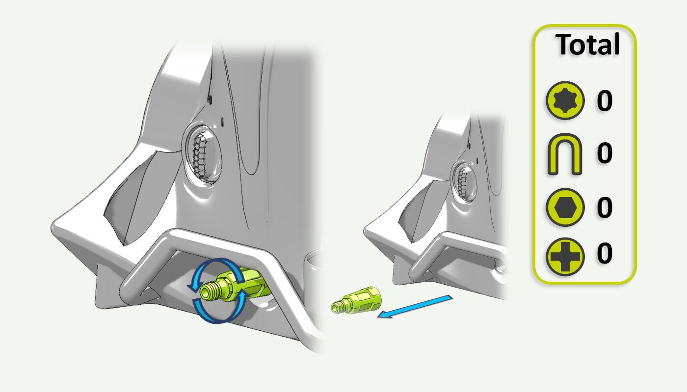
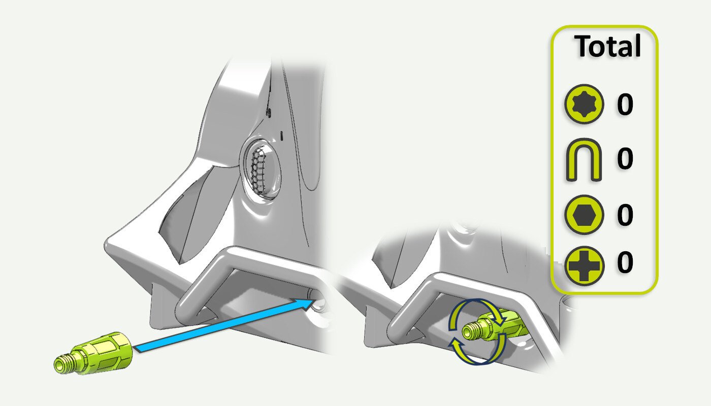
01. Remove water filter
Unscrew the water filter.
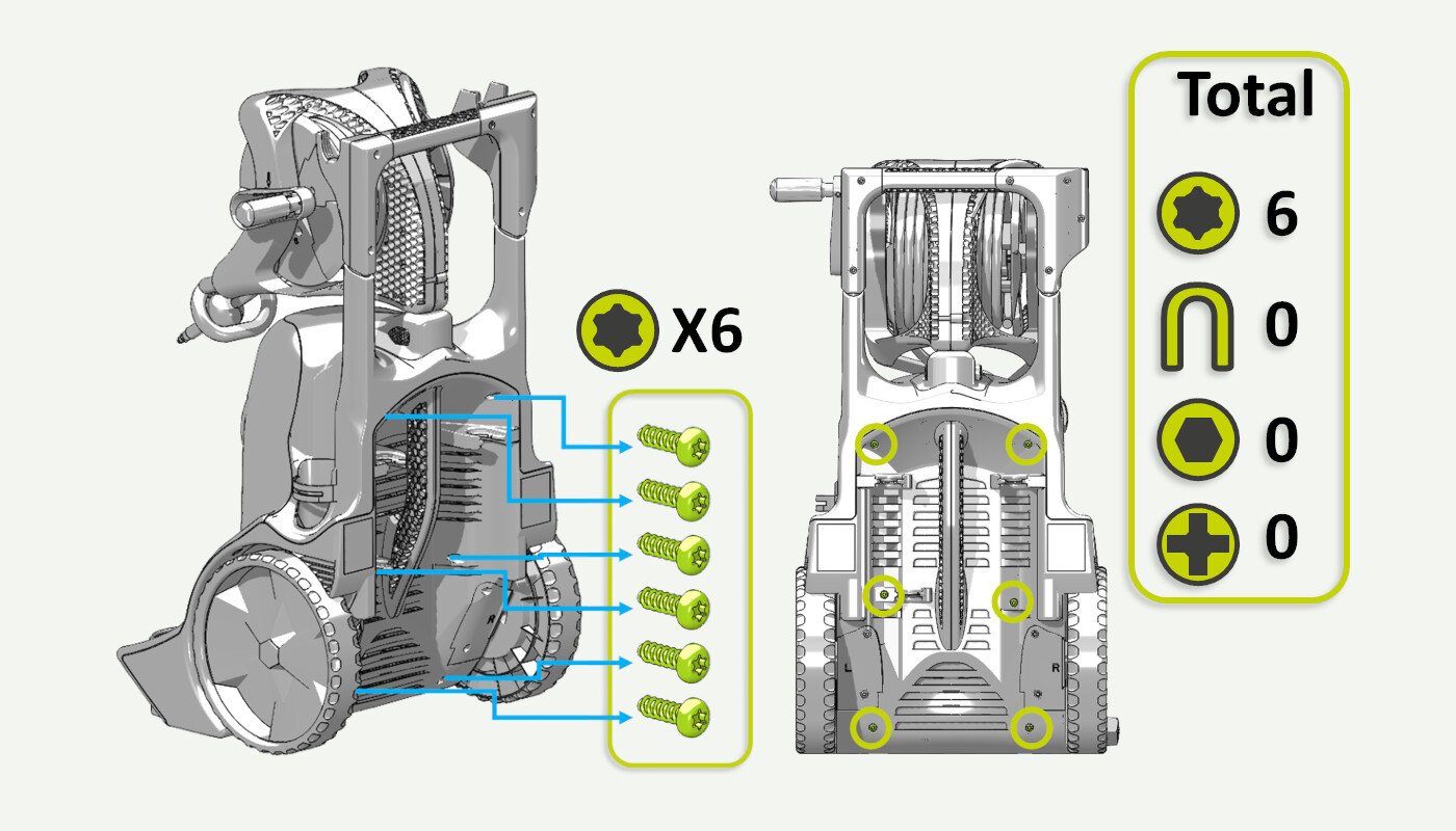
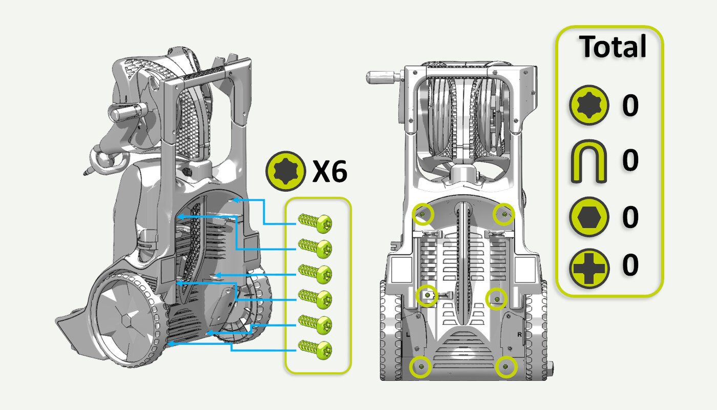
02. Remove screws from the back cabinet
Unscrew 6 T25 screws from the back cabinet. (Picture 1)
Note: Machines produced in 2024 or later have 3 extra screws in addition to picture 1. (Picture 2)
Picture 1:
Picture 2 (Master produced in 2024 or later):

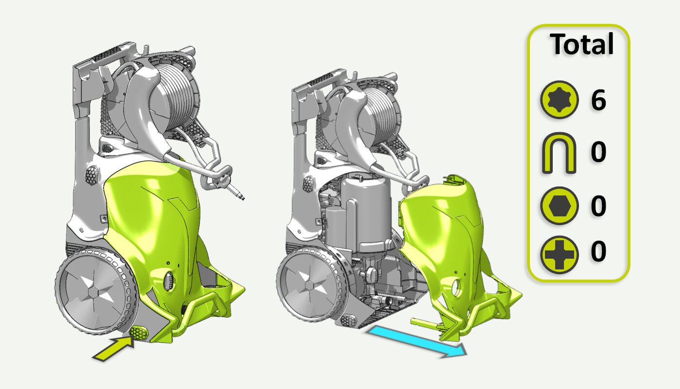
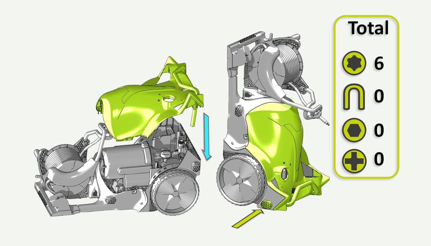
03. Remove the front cover
Push the front brace release button and pull the front cover off.
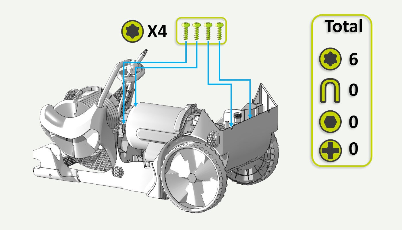
04. Remove screws from the motor/pump
Unscrew 4 T25 screws securing the motor/pump.
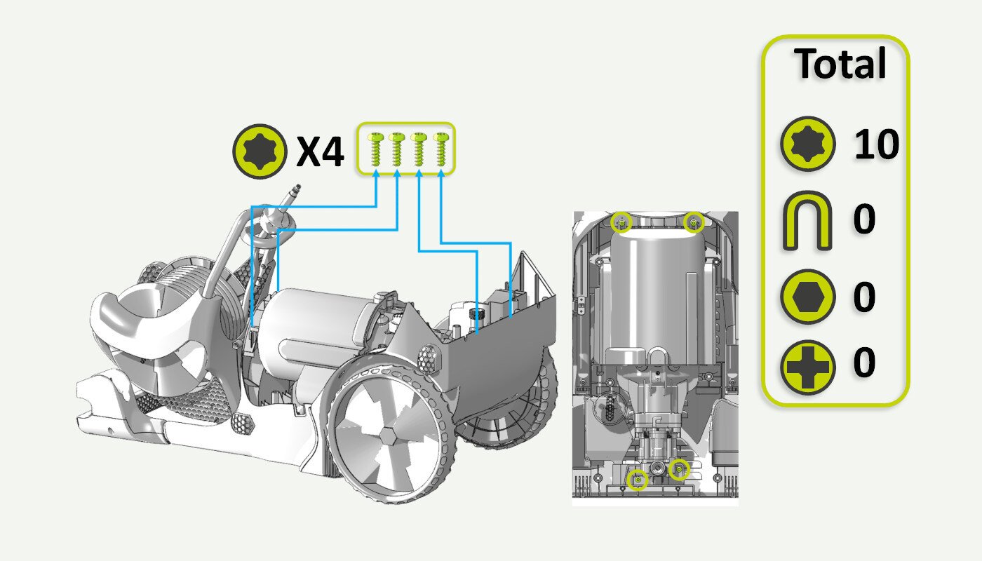
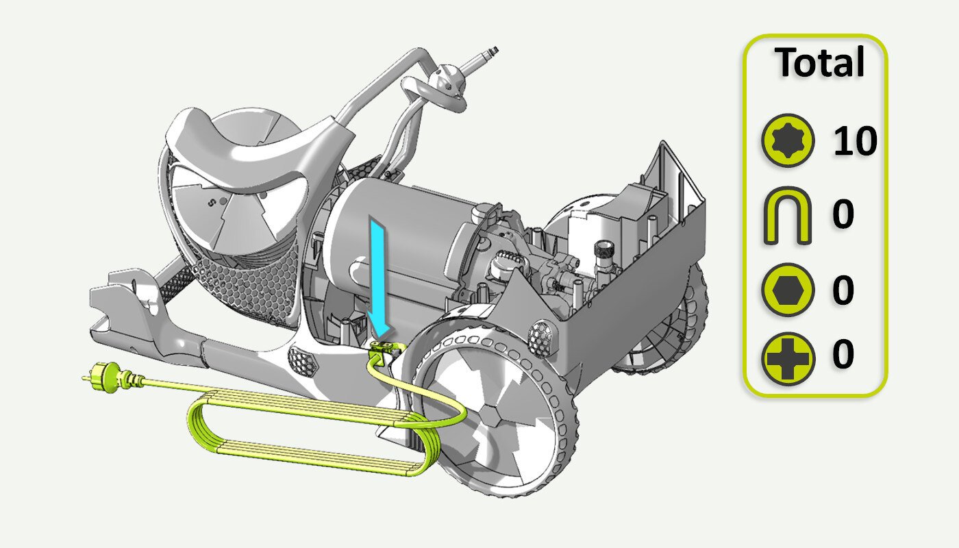
05. Release cable strain relief
Release the cable strain release from the back cabinet.
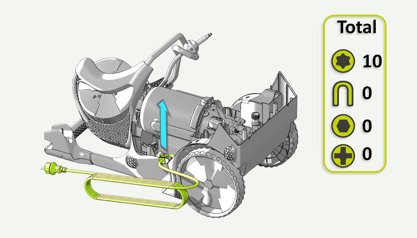
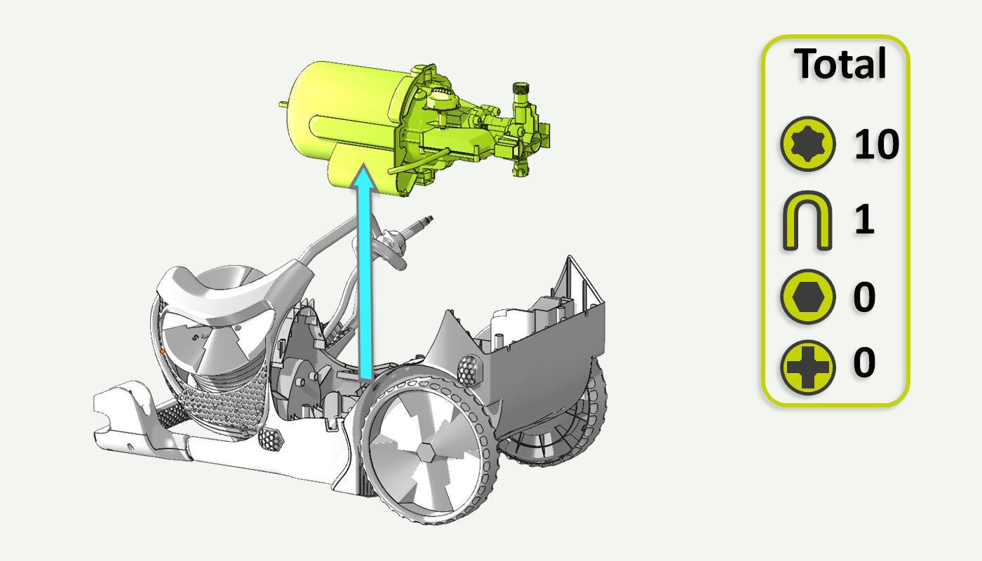
06. Lift the motor/pump unit
Carefully lift the motor/pump so that it sits at an angle.
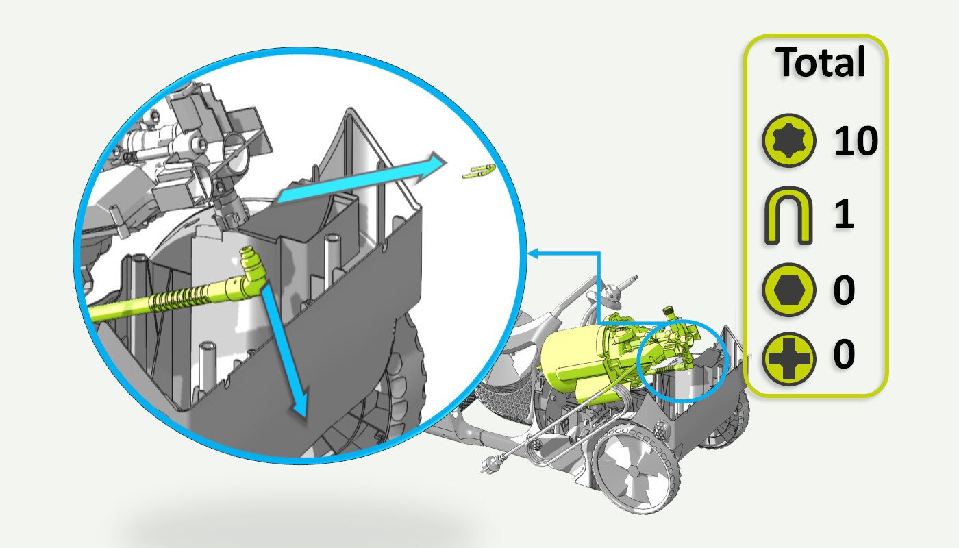
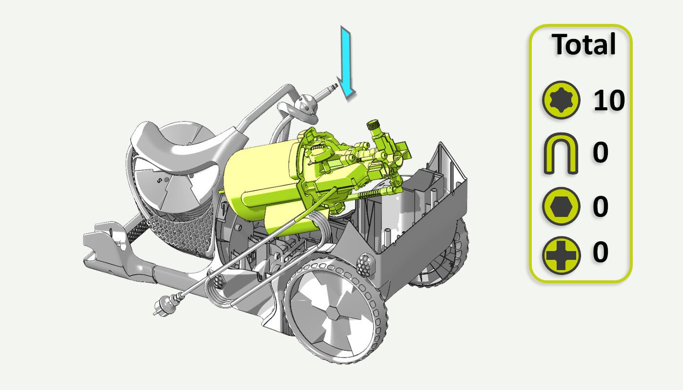
07. Release the internal hose
Carefully use a flat screwdriver or a small knife to release the U-pin securing the internal hose to the pump outlet.
Pull the hose from the pump head.
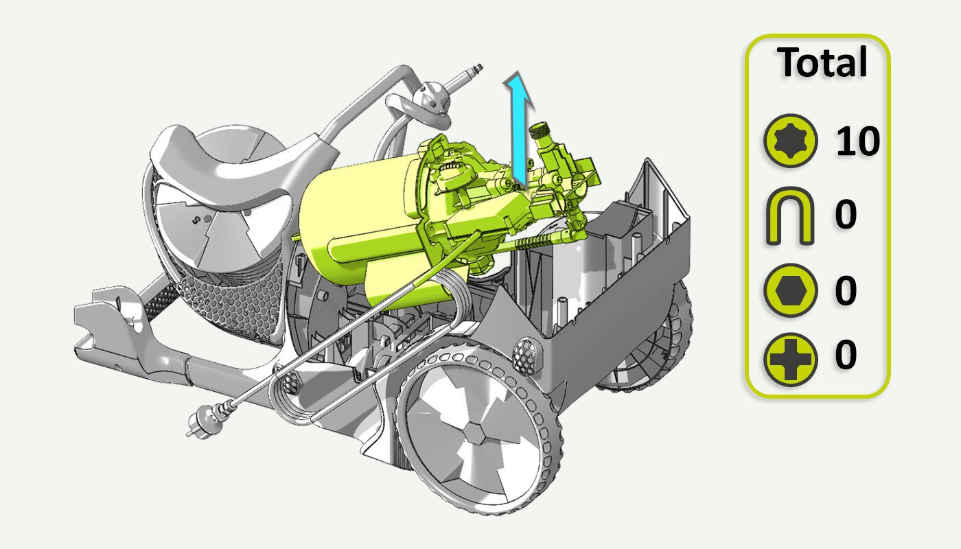
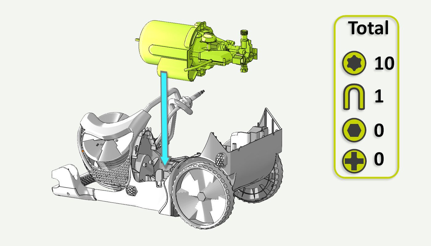
08. Lift the motor/pump
Carefully lift the motor/pump out of the cabinet.
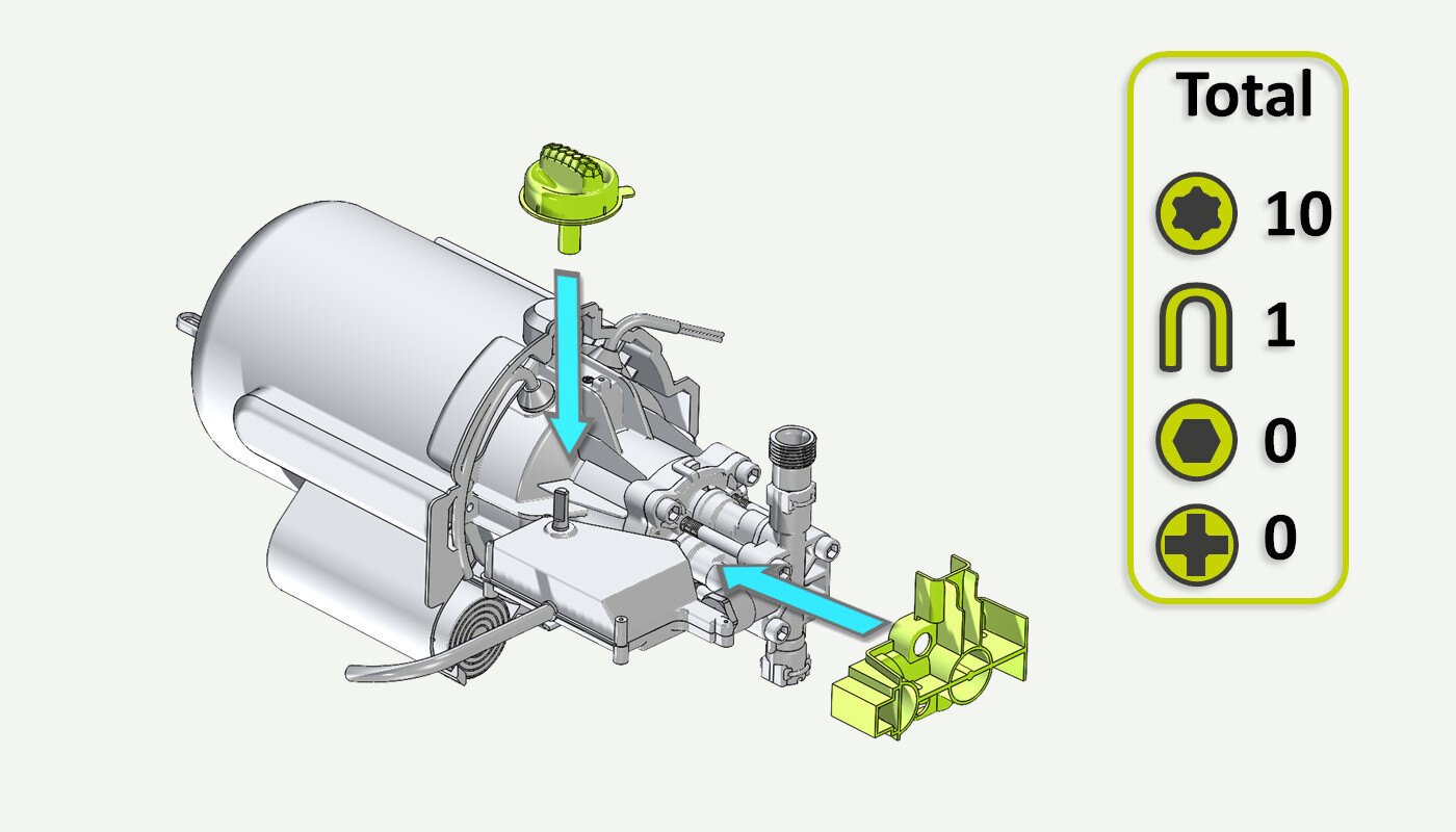
09. Remove parts
Remove the pump head cover and the on/off knob.

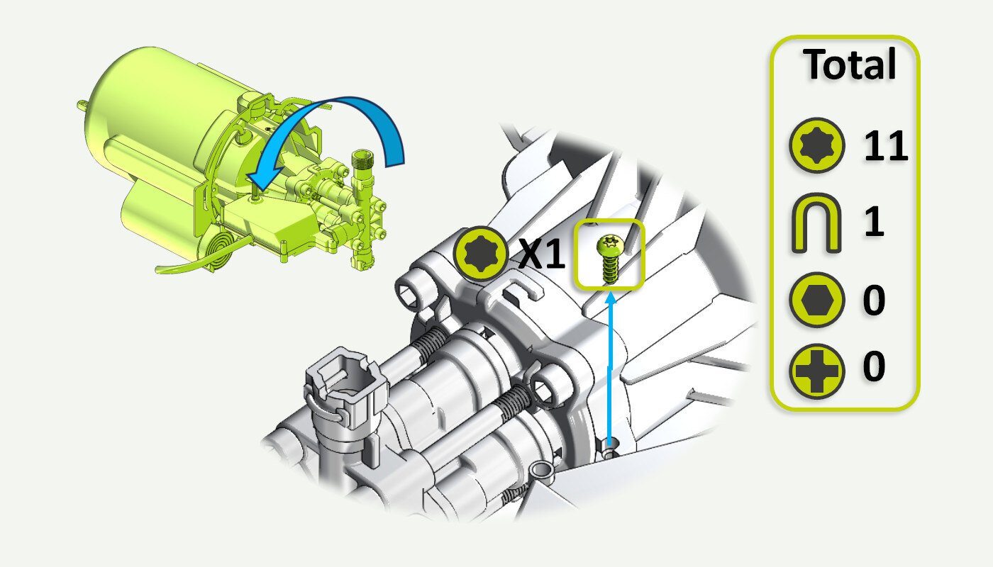
10. Remove screw holding the switch box
Rotate the motor/pump so that you gain access and unscrew the T25 screw securing the switch box.
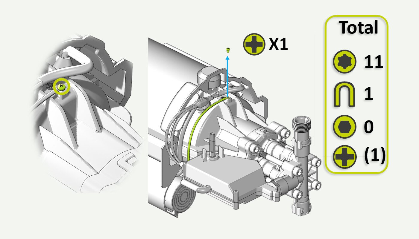
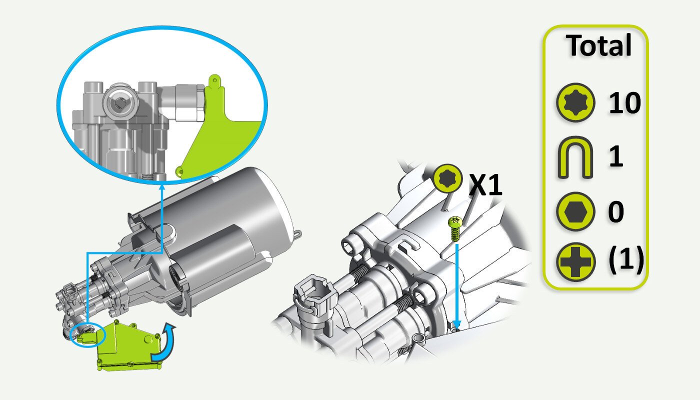
11. Remove the screw holding the grounding cable
Remove the screw holding the grounding cable and move the cable out of the way.
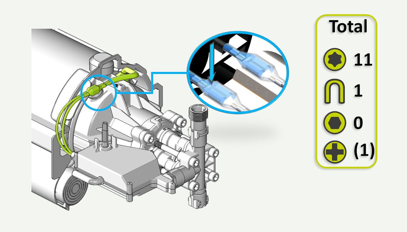
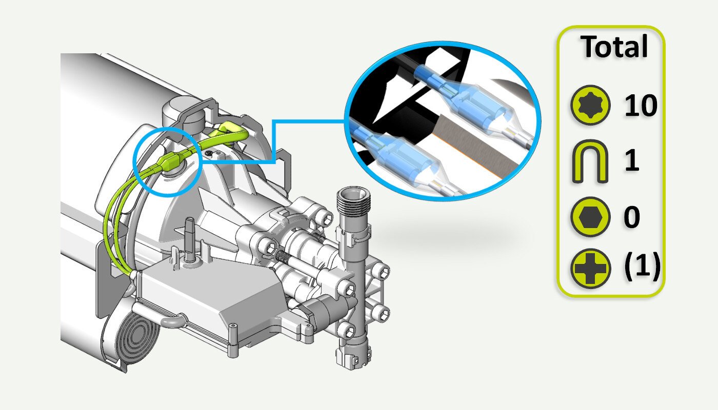
12. Release the motor power cables
Release the motor power cables. The cables are connected with spade contacts. Push down the small locking tab (blue arrow) and gently pull the spade contacts apart.
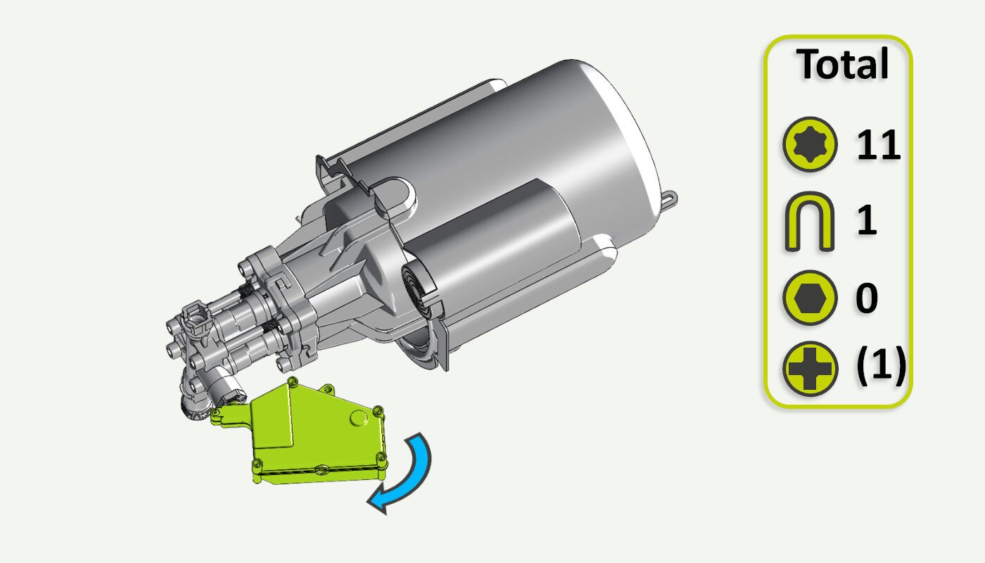
13. Remove switch box
Remove the switch box by pulling it in the direction indicated. It is press-fitted onto the start/stop valve on the pump and will release with a pop.
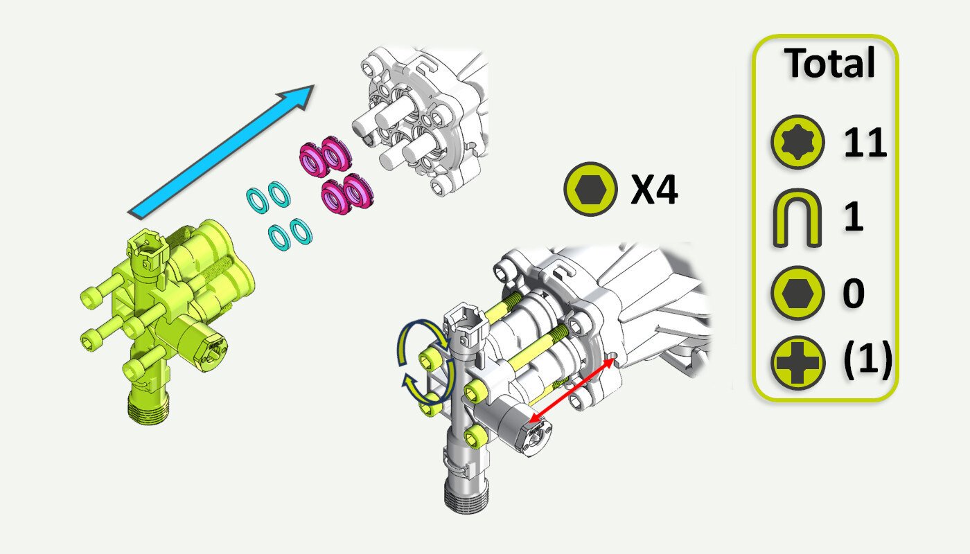
14. Unscrew the screws securing the pump head
Use a 6 mm hex/Allen key to remove 4 screws securing the pump.
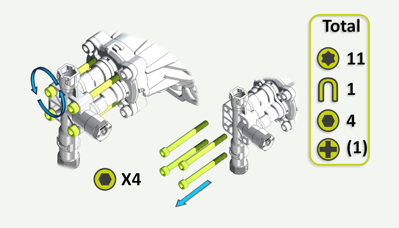
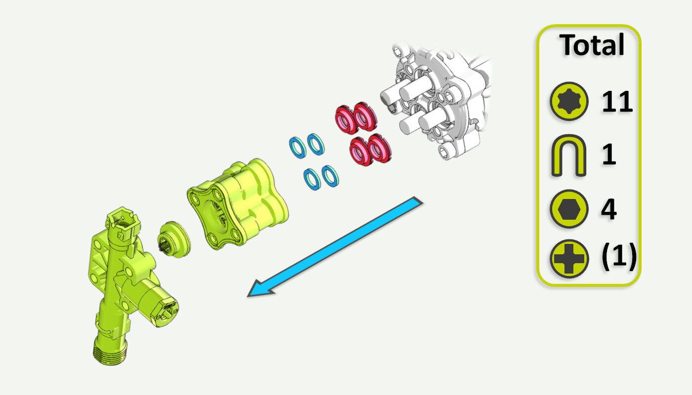
15. Remove the pump assembly
The pump assembly can now be pulled off the piston housing. The brass rings (pink) are reused as these do not experience any wear.
For the P80 models there is also a set of 4 backing rings (white, shown as blue on illustration), these should also be reused when mounting the 5 year service kit on this model.
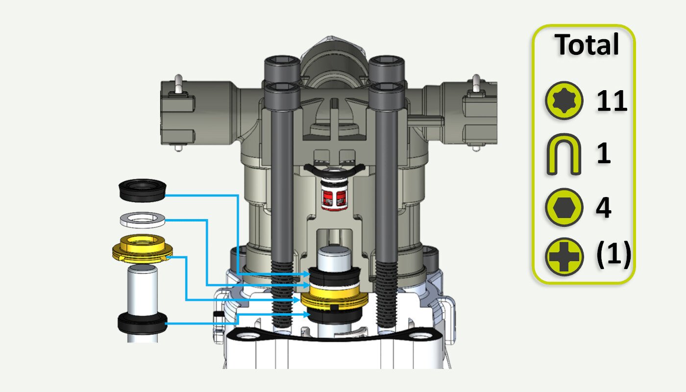
16. Service kit assembly
If there are any loose seals or backing rings, please study the below picture for the correct assembly order. Only the P80 models have the white backing ring (number 2 from the top).
17. Fit the service kit to the piston housing
The brass rings go first followed by the plastic backing rings (only P80) onto the piston housing. Then carefully fit the 5 year service kit onto the piston housing. Make sure that the start/stop valve is aligned with the notch for the switch box (red arrows). Fasten the 4 hex screws and retighten them in an X pattern.
18. Refit the switch box
Attach the switch box to the pump. It requires a fair amount of pressure to get the box firmly seated on the start/stop valve. It should pop into place.
Secure the switch box with a T25 screw.
19. Reattach the power cables
Reattach the power cable by pushing the male spade connector into the female spade connector. Give it a light tug to check that they are securely connected. Make sure that the rubber cover is protecting the spade contacts to prevent short circuits and water ingress.
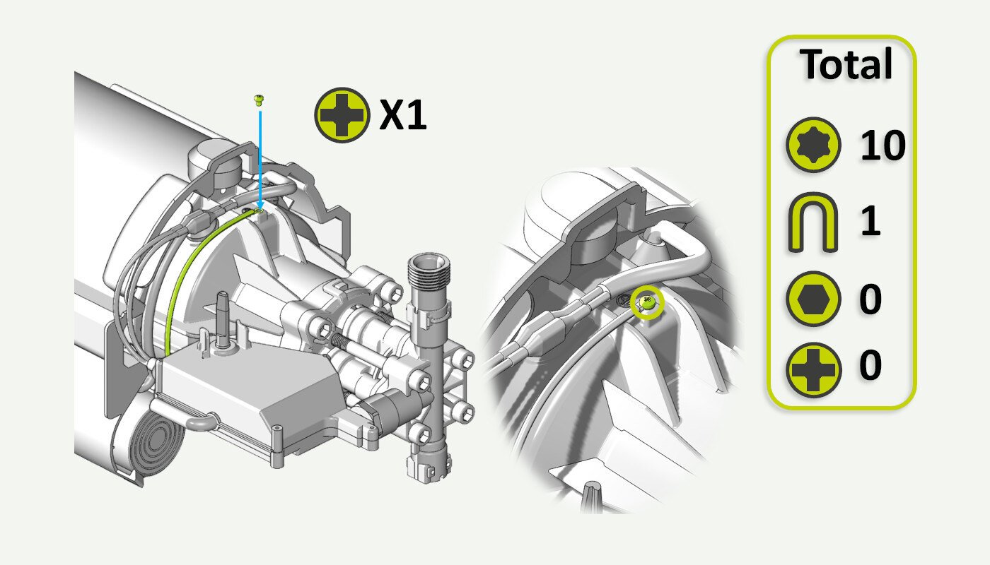
20. Reattach the grounding cable
Place the green-and-yellow grounding cable as indicated in the picture and then secure it with a Phillips/cross head screw.
21. Fit on/off knob and pump head cover
Reattach the pump head cover and the on/off knob.
22. Put the motor/pump back into the rear cabinet
Carefully lower the motor/pump back into the rear cabinet. The water inlet should be pointing upwards.
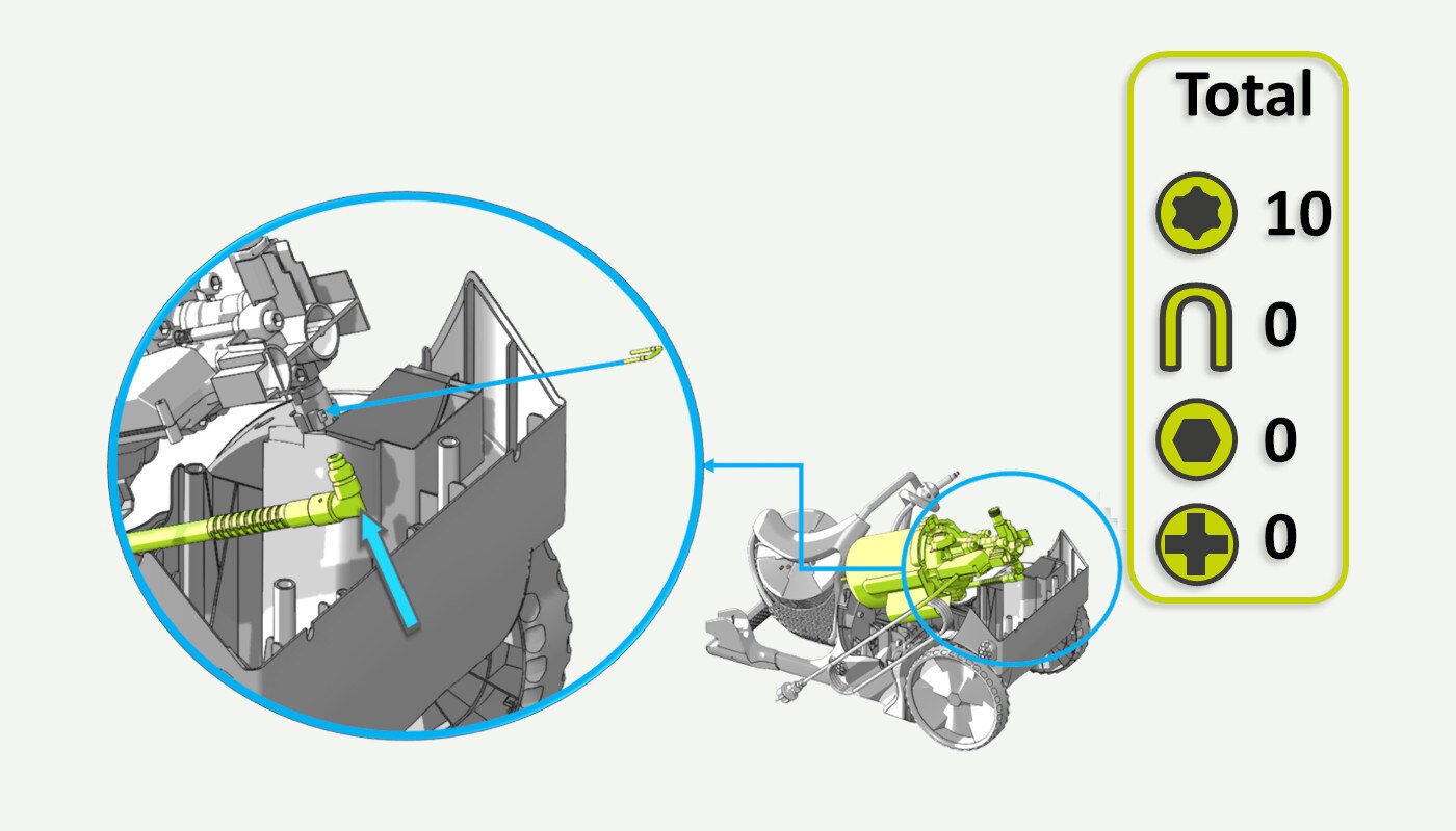
23. Attach the internal pressure hose
With the motor/pump at an angle, reattach the internal high-pressure hose to the pump head.
Secure the hose using a U-pin. Some force may be needed to properly secure the U-pin to the pump head.
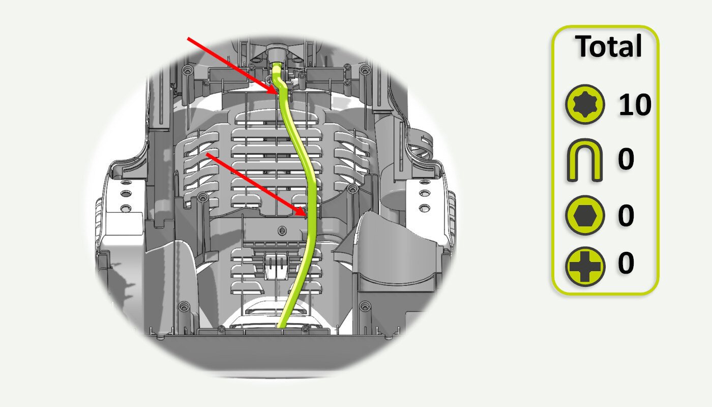
24. Align the internal pressure hose
Make sure that the internal high-pressure hose runs through these two depressions in the back cabinet (red arrows). If you are unable to fit the motor/pump properly then lift it up and check that the internal hose is routed as indicated in this picture.
25. Align the motor/pump
If the previous step was successful, the motor/pump unit should now fit correctly in the back cabinet.
26. Fix the cable strain relief
Reattach the cable strain relief into the slot in back cabinet.
27. Secure the motor/pump
Secure the motor/pump unit using 4 T25 screws. 2 screws on top of the motor cowling and 2 screws on the pump head cover.
28. Attach the front cover
Put the front cover back onto the pressure washer. This is easiest with the pressure washer lying flat. A bit of work may be needed to get it to align perfectly with the back cabinet, take your time. Push the front brace release button to allow for a correct alignment of the brace. When you are happy with your alignment, raise the pressure washer to the upright position.
29. Fasten the front cover
Secure the front cover with 6 T25 screws from the backside of the pressure washer. (Picture 1)
Remember the 3 extra screws in addition if you have Master produced in 2024 or later. (Picture 2)
Picture 1:
Picture 2 (for Master produced in 2024 or later):
30. Reattach the water filter
Check that the filter cassette is clean and without damage. (the cassette can be removed from the filter and cleaned if necessary)
Reattach the water filter to the water inlet.
31. First start after service
Congratulations on finishing the service on your AVA Master.
It is now time to do the first start after service.
- Begin by connecting the pressure gun to the hose.
- Connect the water. Make sure there is no water leaking from the inside or anywhere else on the pressure washer. We recommend placing the machine in a dry location, such as on a piece of cardboard.
- Pull the trigger and let the water flow until there is no more air coming out.
- Connect the power cord.
- Turn on the pressure washer.
- Pull the trigger and let water run for a minute before connecting a nozzle.
- Connect the nozzle.
- Use the pressure washer and make sure it is operating normally.
Troubleshooting
Water is leaking from the inside
- Disconnect the power and open the pressure washer to locate the leak.
- Take necessary action to remedy any leaks.
Motor runs and won't stop when you release the trigger
- This is most likely due to an improper seating of the switch box on the start/stop valve.
- Open the machine and check that the switch box is correctly seated.
The pressure washer won't turn on
- Check that the power cable is connected.
- Check that the circuit breaker has not been tripped.
- Check that the fuse in the power plug is intact (UK models only).
- Open the machine and check that all the internal cabling is connected.
Poor performance/pressure
- Improper assembly or dirt/debris in the pump.
- Check the pump, especially the main valve, for foreign objects or debris.
- Make sure that the spring in the main valve is correctly seated and working as intended.
Motor is making a humming noise and is not able to start
- Check that the capacitor is connected to the motor.
- It should be connected with one white and one black cable.
Terms/conditions apply, read more here


